 |
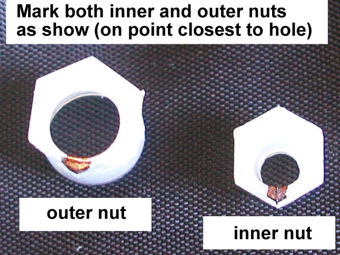 |
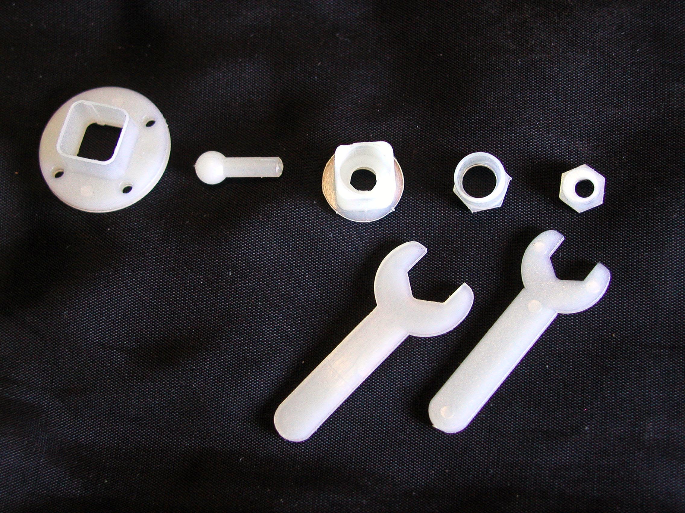
| Picture 1 - The parts and tools supplied | Picture 2 - Mark the adjustable nuts on the corner that is nearest to the hole |
 |
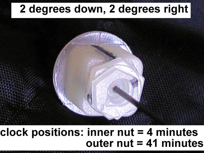 |
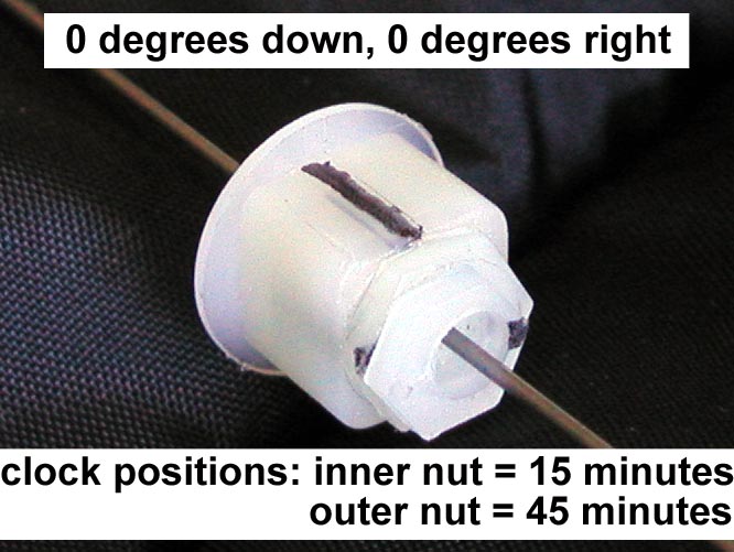
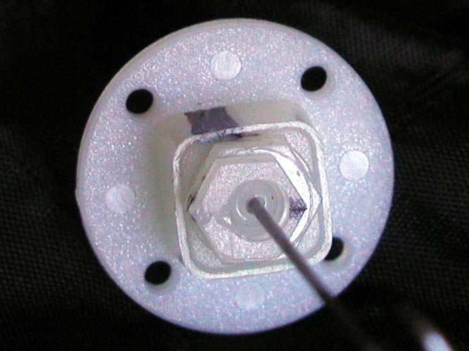
| Picture 3 - The button assembled, note the mark on the grove in the top, this marks the top "12 o'clock" position for all "clockings" | Picture 4 - Here the "clockings"
are for: 2 degrees down and 2 degrees right thrust. Use the KP clocking table for other angles. |
 |
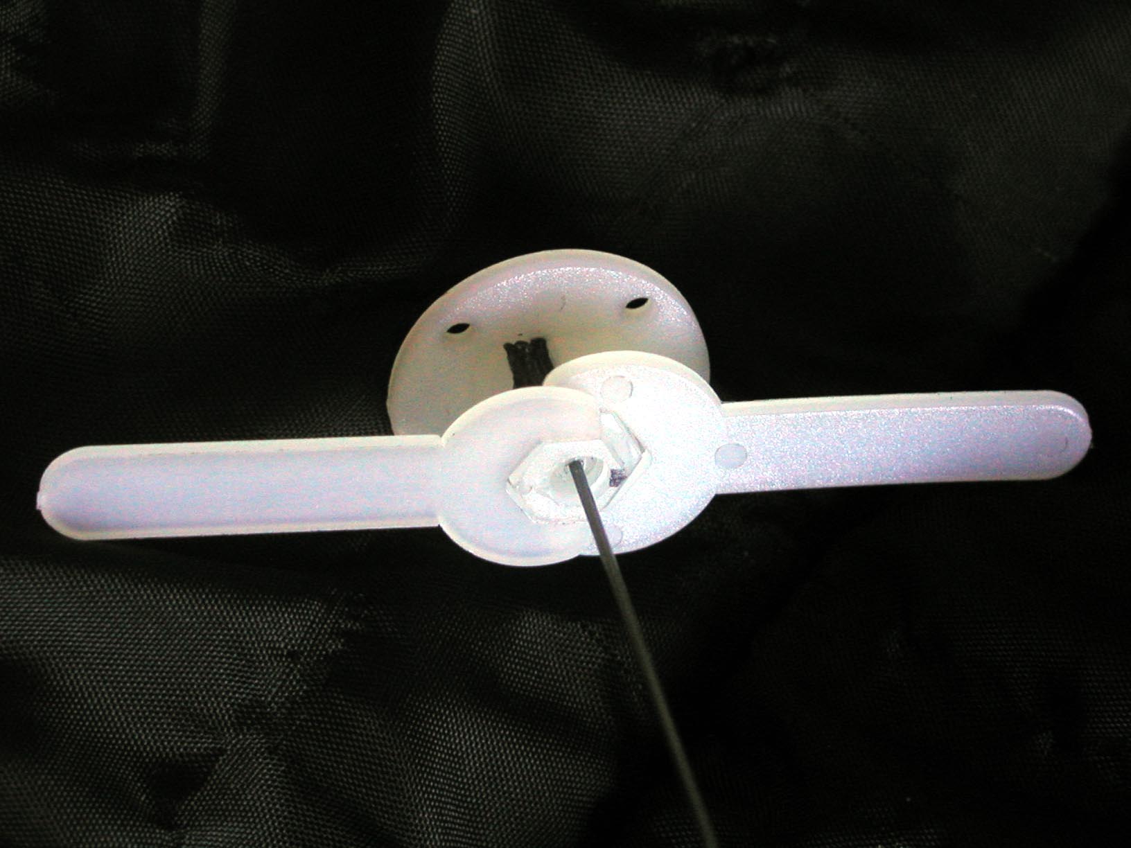 |
| Picture 5 - This is another picture of the unit clocked for 0 degrees down and 0 degrees right, this time with the optional locator ring | Picture 6 - Using the wrenches for 0-0 thrust clockings : inner 14 minutes, outer 45 minutes |